FAREC (Finite Automata and Regular Expression Converter) is an educational tool designed to demonstrate the algorithms used to convert between finite automata and regular expressions.
FAREC was created during the third year of my MSci Computer Science degree at King’s College London, for the module 6CCS3PRJ - Individual Project. The title of my project was “Implementing algorithms connecting finite automata and regular expressions”. My supervisor for the project was Dr. Agi Kurucz.
Overview
FAREC allows you to create a finite automaton/regular expression and then convert it into an equivalent regular expression/finite automaton. Each step of the conversion process is shown.
To convert finite automata into regular expressions, FAREC uses the State Elimination with GNFAs algorithm. To convert regular expressions into finite automata, FAREC uses the McNaughton–Yamada–Thompson algorithm (also known as Thompson’s construction algorithm).
FAREC was written in the Java programming language, using the JavaFX platform for the GUI and the JUnit framework for testing. I also used Scene Builder to help me create the GUI.
In the following sections, I will discuss how the different components of the program were implemented.
If you are interested in the project or the theory behind it (including the two aforementioned algorithms), you can read the full report or watch the project video.
Table of Contents
- Regular Expressions
- Parse Trees
- Parser
- Graphical Finite Automata
- Smart Finite Automata
- Controllers
- Settings
- Testing
- Documentation
Regular Expressions
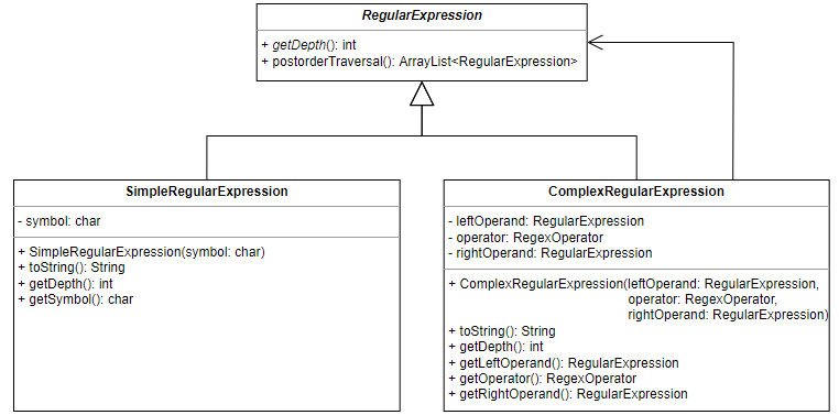
Regular expressions are represented by the abstract RegularExpression class
and its two subclasses. The SimpleRegularExpression subclass represents the
base case in the inductive definition of regular expressions. A simple regular
expression is a regular expression consisting of a single symbol. The
ComplexRegularExpression subclass represents the inductive cases in the
inductive definition of regular expressions. It consists of a regular expression
operator (a regex operator) applied to one or two RegularExpression objects
(depending on the type of operator). The RegularExpression objects, referred
to as the left operand and right operand respectively, may themselves also be
complex regular expressions. This allows for a tree-like structure where regular
expressions are composed of other regular expressions. This makes dealing with
regular expressions significantly easier. The tree-like structure of regular
expressions is made explicit by the ParseTree class.
Parse Trees
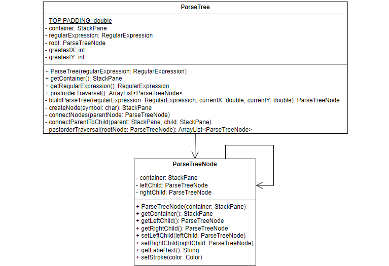
The ParseTree class represents a regular expression parse tree, which is a
tree where internal nodes are regex operators and leaf nodes are symbols. The
parse tree is created in two stages. First, the buildParseTree method creates
all the nodes of the tree and places them in the correct positions. The
connectNodes method then connects the nodes with edges. The nodes of the parse
tree are represented by the ParseTreeNode class, which stores the visual
representation of the node as well as references to the children of the node.
The buildParseTree method
The buildParseTree method is a recursive method that builds the parse tree for
a given regular expression. It also takes in two additional variables,
currentX and currentY, which are used to keep track of the position of the
root node of the current parse tree.
If the given regular expression is a simple regular expression, a leaf node representing the regex symbol is created and moved into position. If the regular expression is a complex regular expression, an internal node representing the regex operator is created instead. The method is then recursively called with the left and right operands of the complex regular expression to build the left and right subtrees. Before this can happen however, the program must first calculate the position of the root node of the subtrees.
The vertical offset from the current position is always the same, but the horizontal offset varies and needs to be calculated. If the regex operator is the star operator, this task is trivial: since the star operator is unary, there is no need for a horizontal offset and the root node of the subtree can be placed directly below the current position. However, if the regex operator is the concatenation or union operator, the horizontal offset needs to be calculated such that the subtree of the left operand and the subtree of the right operand do not overlap. This will depend on the number of leaf nodes in the subtrees.
The parse tree is built top-down, which means the method does not know the number or structure of leaf nodes in the lower levels of the tree. As such, it has to assume the worst case scenario: that the parse tree will be a perfect tree (meaning that all interior nodes have two children and all leaf nodes are at the same level). As the number of leaf nodes doubles with depth, so will the horizontal offset. If k is the horizontal offset needed for a subtree with a max depth of 1, the horizontal offset x needed for a subtree with max depth d > 1 can be calculated as follows: x = 2d−1 × k.
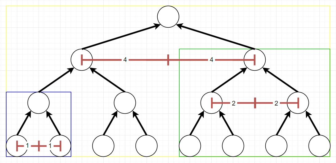
For example, consider the nodes in the blue rectangle in figure above. The horizontal offset needed for a tree with a depth of 1 is 1 square. If the max depth of the tree increases to 2 (green rectangle), the horizontal offset needed is now 22−1 × 1 = 2 squares. Finally, if the max depth of the tree is 3 (yellow rectangle), the horizontal offset needed is 23−1 × 1 = 4 squares.
Once the method has calculated the horizontal offset needed, it first subtracts
it from the currentX when building the left operand subtree and then adds it
to the currentX when building the right operand subtree. Having built the
subtrees and set the children of the operator parse tree node accordingly, the
method then returns the operator node of the tree being built. The last operator
node returned will be the root node of the parse tree for the whole regular
expression.
The connectNodes method
Although the ParseTreeNode class keeps references to its children, its
container variable (which stores the graphical representation of the node)
does not include edges between the nodes, just the nodes themselves. It is the
responsibility of the connectNodes method to visually connect the nodes by
adding edges to the parse tree. This method is also recursive. Given a
ParseTreeNode as input, it first connects the node to its children using the
connectParentToChild helper method, and then recursively calls itself on both
children.
Parser
The RegularExpression class represents regular expressions and the ParseTree
class displays them visually, but it is the Parser class that creates them in
the first place. It contains several methods for dealing with strings
representing regular expressions (regex strings).

The isValid method
The isValid method checks that the given regex string is valid, i.e. that it
contains only symbols from the alphabet Σ, the empty string and empty set
symbols, the available regex operators, and brackets. The default symbols for
the regex operators in the program are as follows:
- The Kleene star regex operator uses the asterisk symbol *.
- The concatenation regex operator uses the vertical pipe symbol |.
- The union regex operator uses the plus symbol +.
The isValid method also checks that the number and placement of brackets is
valid. It returns a pair (K, V), where K is a boolean representing whether
the regex string is valid or not, and V is an error message for the case that
the regex string is invalid.
The removeOuterBrackets method
The removeOuterBrackets method removes the outer brackets from a string.
Regular expressions with outer brackets such as
(a+b)
or even
((a+b))
are valid, but the outer brackets are superfluous and can be safely removed
without changing the regular expression. The string remains unchanged if it does
not contain outer brackets - for example, the regex string
(a+b)|(c+d)
would not have its brackets removed, since the opening bracket at the start and
the closing bracket at the end are not linked and therefore not considered outer
brackets.
The findRootIndex method
The findRootIndex method takes in a regex string that has had its outer
brackets removed and finds the index of the root regex operator of the regular
expression. The root regex operator is the operator that will be the root node
in the regular expression’s parse tree. To find this root operator, the method
looks for regex operators that are not contained within any brackets. If such an
operator is found, its index is returned. For example, in the regular expression
(a+b)|d,
the root operator is the concatenation operator at index 5.
Problems arise when the regex string has more then one eligible root operator. For example, in the regular expression a+b*|c, all three operators are not contained within any brackets and so appear to be eligible root operators. In practise, the union and concatenation operators could be the root operator, but taking the star operator as the root would result in an invalid regular expression being formed.
One solution to this problem would be to enforce a restriction on the regex strings such that there is always only one regex operator that is not contained within brackets. The regular expression from the previous example could then be written as a+((b*)|c). This solution is not desirable, as it places the burden on the user to add the correct brackets.
Instead, the findRootIndex method considers the precedence of the regex
operators when looking for the root operator. The star operator has the highest
precedence and the union operator has the lowest precedence, with concatenation
being in the middle. The root operator can now be defined as the lowest
precedence operator that is not contained within brackets. Using this new
definition, the root operator in the regular expression
a+b*|c
is the union operator. This makes the regular expression equivalent to
a+((b*)|c),
but without forcing the user to explicitly add in those extra brackets.
The updated definition of the root operator creates a new issue: regular expressions such as a|b|c contain several operators that are not contained within brackets and have equal precedence. A tie-breaker must be added to resolve situations such as this.
If there are multiple candidates for the root node operator, all with equal precedence, then the right-most operator is chosen as the root. This means that regular expressions such as a|b|c are considered to be equivalent to (a|b)|c and not a|(b|c). Thinking of a|b|c as appending c to a|b seemed more natural to me than prepending a to b|c.
The parseRegexString method
Having defined the previous methods, the parseRegexString method can now be
discussed. This method takes in a regex string and returns its equivalent
RegularExpression object, or throws an IllegalArgumentException if the regex
string does not represent a well-formed regular expression. The
parseRegexString method first checks that the regex string is valid using the
isValid method. The removeOuterBrackets method is then used to strip the
regex string of any outer brackets.
At this point, the regex string is checked to see if it matches a simple regular
expression. If this is the case, a SimpleRegularExpression object is created
and returned, and the method terminates. Otherwise, the regex string must
represent a complex regular expression. The root operator of the complex regular
expression is found by the findRootIndex method. Everything to the left of the
root operator is taken to be the left operand. The left operand is parsed into a
RegularExpression object by recursively calling the parseRegexString method.
The root operator of the regex string is then checked. If the operator is
concatenation or union, the complex regular expression should have a right
operand. Everything to the right of the root operator is taken to be the right
operand and parsed into a RegularExpression object. Finally, the method
creates and returns a new ComplexRegularExpression object using the parsed
left and right operands as well as the root operator.
Throughout the execution of the parseRegexString method, the regex string is
checked to ensure that it represents a well-formed regular expression. One
example of such a check is that, in a well-formed regular expression, if the
root operator of the regex string is the star operator, the regex string
shouldn’t have a right operand. If a right operand is found, the method will
throw an exception. The error message of the exception is displayed to the user
and describes the cause of the problem, highlighting which part of the regex
string is to blame. This allows the user to easily identify mistakes in the
regex string.
The simplifyRegexString method
The Parser class has one more method: the simplifyRegexString method. This
method takes as input a regex string representing a regular expression, and
returns as output a regex string representing the same regular expression, but
with all unnecessary brackets removed. For example, given the regex string
(((a*)|b) + (c|(d*))),
the simplifyRegexString method returns the equivalent regex string
a*|b+c|d*.
The method searches the regex string for a pair of brackets to remove. If a pair
of brackets can be found, they are removed the from regex string, which is then
parsed by the parseRegexString method. The resulting regular expression is
compared to the original regular expression, represented by the original regex
string. If the two expressions are equivalent, the new regex string is kept:
otherwise, it is discarded. The method then searches for another pair of
brackets to remove. If such a pair cannot be found, the regex string cannot be
simplified further and the method terminates.
Graphical Finite Automata
Graphical finite automata are used when converting regular expressions into finite automata. The construction of a finite automaton from a regular expression follows defined rules and the finite automaton produced has a fixed structure. Emphasis is placed on the presentation of the finite automaton, for example ensuring that it is always centred on the screen. The components of a graphical finite automaton can be manipulated during its construction to position them correctly.
Because they are used solely for presentation, graphical finite automata concern themselves with just the graphical aspect of a finite automaton. They do not keep track of their components: a graphical finite automaton does not know what states or edges belong to it, with the exception of the initial and final state. Each component of a graphical finite automaton is isolated from the other components and does not know about their existence.
The GraphicalFiniteAutomaton class
Graphical finite automata are represented by the abstract
GraphicalFiniteAutomaton class, which is extended by two subclasses. The
SimpleGraphicalFiniteAutomaton subclass is used for simple regular expressions
and consists of only two states with a single edge between them. The
ComplexGraphicalFiniteAutomaton subclass is used for complex regular
expressions and consists of multiple states and edges.
The states and edges of a graphical finite automaton are stored in its
container variable. The GraphicalFiniteAutomaton class also contains methods
for enabling and disabling the initial and final states of the automaton: this
is necessary when the automaton is used in the construction of other automata.

Graphical States and Graphical Edges
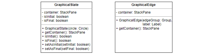
Graphical finite automata are composed of graphical states and graphical edges,
represented by the GraphicalState class and the GraphicalEdge class
respectively. Both have a container variable that holds the components that
make up the state or edge. The GraphicalState class also contains methods for
changing the state to an initial or final state. These methods pass on the
request to the GraphicalFiniteAutomatonBuilder class.
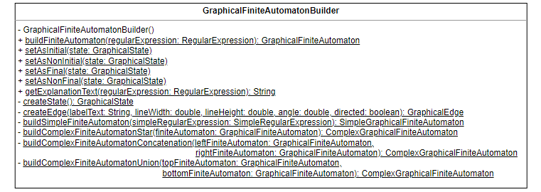
The GraphicalFiniteAutomatonBuilder class
The GraphicalFiniteAutomatonBuilder class is responsible for building and
manipulating graphical finite automata and their components. The most important
method in this class is the buildFiniteAutomaton method, which takes as input
a RegularExpression object and returns as output a corresponding
GraphicalFiniteAutomaton object.
This is a recursive method, which first builds the finite automata/finite
automaton for the operands/operand of the regular expression and then combines
them/extends it according to the construction rule of the regex operator used in
the regular expression. Each regex operator has its own construction rule
defined in its own helper method. These methods manipulate the initial states,
final states and container variables of the given finite automata to create a
new complex finite automaton. The base case of the recursion is when the regular
expression is a simple regular expression, in which case a
SimpleGraphicalFiniteAutomaton is constructed.
The GraphicalFiniteAutomatonBuilder class also contains methods for creating
graphical states and edges, for adding and removing the marking that sets a
state apart as an initial or final state, and for generating text explaining how
a finite automaton was constructed.
Smart Finite Automata
Smart finite automata are used when converting finite automata into regular expressions. Unlike graphical finite automata, smart finite automata do not have a fixed structure. They are created and manipulated by the user rather than the program. As such, there is no need to centre them or position their components in precise locations: the user is free to move the components around as they see fit.
This requires the finite automata to be ‘smarter’ than their graphical counterparts; smart finite automata keep track of their states and edges. The components themselves are also smarter; smart states know what edges are connected to them and smart edges know what states they connect.
The SmartFiniteAutomaton class
Smart finite automata are represented by the SmartFiniteAutomaton class. Just
like graphical finite automata, smart finite automata keep their components in
their container variable. They also keep a list of states and edges belonging
to the finite automaton, in addition to the initial state and final state.
Smart finite automata are also linked to the CreateFAScreenController
responsible for creating them and the ConvertFAScreenController responsible
for converting them into regular expressions. Whenever a state or edge is added
to the finite automaton, the automaton will ask the appropriate controller to
set the user interaction behaviour for that state or edge. The user interaction
behaviour defines how the user can interact with the state or edge through mouse
clicks and mouse drags, as well as what kind of actions the user can perform.
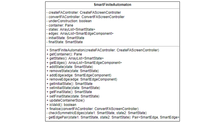
The SmartFiniteAutomaton class has methods for adding and removing states and
edges. When a state is removed from a smart finite automaton, all edges
connected to that state are also removed. Smart finite automata are limited to
having at most one edge in each direction between any two states. Displaying
multiple edges between two states in the same direction would quickly become
problematic. Instead, a common notation is adopted where an edge may have
multiple symbols on its label separated by commas.
Two states may still have two edges between them, as long as the edges are going
in opposite directions. These edges are referred to as symmetric edges.
Whenever an edge is added to or removed from a smart finite automaton, the
automaton will check for symmetric edges. This is done using the
checkSymmetricEdges method. If the method finds symmetric edges, it will
replace the straight edges with curved ones. This makes it easier to see which
label corresponds to which edge. If there is only one edge between the two
states, the checkSymmetricEdges method ensures that the edge is straight.
One final method of interest is the isValid method, which checks that the
finite automaton created is valid. A valid finite automaton must have an initial
state and a final state. In addition, every state in the finite automaton must
be reachable from the initial state. This is checked by performing a
breadth-first search from the initial state and making sure that every state in
the finite automaton is encountered.
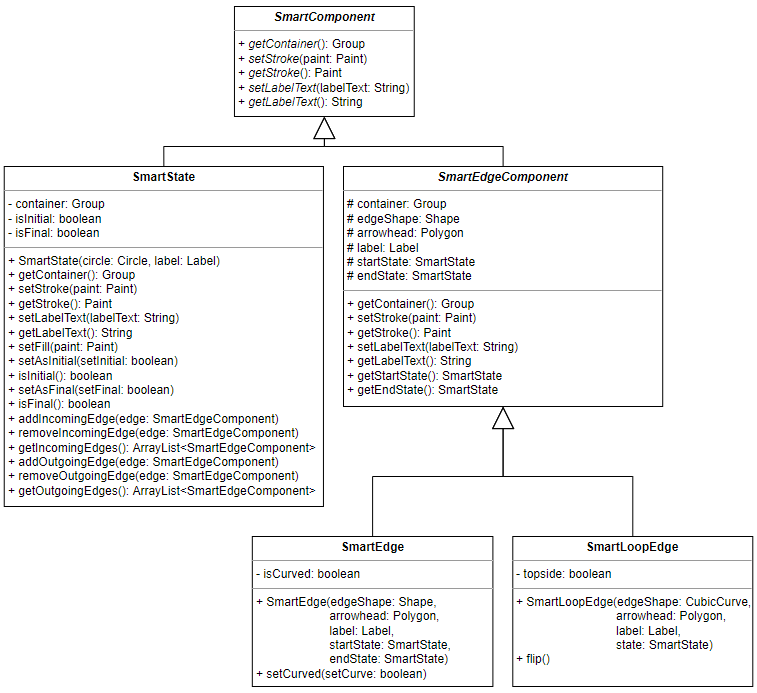
Smart Components
The abstract class SmartComponent represents a component in a smart finite
automaton. It contains methods for that are common to all finite automata
components. A smart component is either a SmartState or a
SmartEdgeComponent.
The SmartState class represents a state in a smart finite automaton. A smart
state keeps track of its incoming and outgoing edges. The SmartEdgeComponent
class is an abstract class representing an edge component in a smart finite
automaton. Smart edge components keep track of the states they are connected to.
There are two types of smart edge components: a SmartEdge and a
SmartLoopEdge.
A smart edge is an edge that connects two different states. In addition to the
variables and methods it inherits from the SmartEdgeComponent class, it also has
an extra method called setCurved that allows the edge to switch between a
straight line and a curve.
On the other hand, a smart loop edge connects a state to itself. In addition to
the variables and methods it inherits from the SmartEdgeComponent class, it
also has an extra method called flip, which changes the position of the loop
edge. The loop edge may be either above the state or below it.
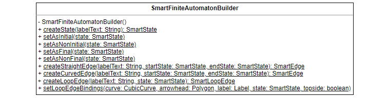
The SmartFiniteAutomatonBuilder class
The SmartFiniteAutomatonBuilder class is responsible for building and
manipulating smart finite automata and their components. It can create smart
states, straight and curved smart edges, and smart loop edges. It contains
methods for adding and removing the marking that sets a state apart as an
initial or final state. It also has a method for setting the bindings for a
smart loop edge (smart loop edges need to have their bindings set when they are
created or when they have their position flipped).
The methods for creating straight, curved and loop edges were particularly difficult to implement. The problem was that, due to the dynamic nature of smart finite automata, the edges had to move along with the states they were connected to.
For straight edges, the first step in achieving this behaviour was to bind the start position and end position of the line to the centre of the start state and end state respectively. This ensured that the length and gradient of the line would change appropriately when either one of the states was moved.
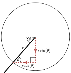
The next step was to move the arrowhead into position, such that it sits on the line with its point touching the circumference of the end state. The arrowhead was bound to the centre of the end state, but with an x-offset and y-offset added to move it from the centre of the state to the circumference. These offsets were calculated by working out the horizontal and vertical components of the radius of the circle at the point where the line crosses the circumference. These offsets are shown in the figure below as dotted red lines. To work out the offsets, the angle θ needed to be calculated.
In order to calculate θ, the translation needed to get from the start state to
the end state had to be determined first. This was calculated from the position
of the two states and stored in the sToEX (for the x-translate) and sToEY (for
the y-translate) variables. It’s important to note that both sToEX and sToEY may
be negative, depending on the positions of the start and end states.
Once these translates have been calculated, the angle θ could be worked out as
tan-1(sToEY÷sToEX).
This could return a negative value - see the figure below - so the absolute
value was used in the calculation of the offsets. The sign on sToEX and
sToEY was then used to decide whether to add or subtract the respective
offsets. For example, if sToEX was positive, that meant that the end state was
to the right of the start state, and so the x-offset needed to be subtracted to
move the arrowhead to the left from the centre of the end state.
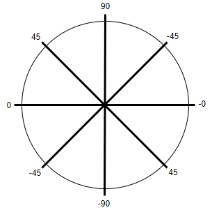
The last step was to work out the angle needed to rotate the arrowhead so that it faced towards the centre of the end state. If the end state was on the right of the start state, the angle was just the true (non-absolute) value of θ; if the end state was on the left side, the angle was 180 + θ (see the figure above for the different angles of θ).
Curved edges use a quadratic Bézier parametric curve segment as their edge and so have an additional control point that defines the shape and position of the curve (note that the control point does not actually lie on the curve itself). This control point also needs to be positioned appropriately (see the figure below). The control point was bound to the centre of the start state, but with an x-offset and y-offset added. Each one of these offsets is made up of two parts:
-
The first part (shown as dotted blue lines in the figure below) moves the control point to the centre of a line between the start state and the end state (this line does not actually exist, but it is shown in the figure as a dotted green line for illustrational purposes). This primary offset was computed by calculating
sToEXandsToEYand then multiplying them by 0.5. -
The second part (shown as dotted red lines in the figure below) moves the control point a constant distance k perpendicular to the line between the two states (in the figure, this distance is shown as a dotted yellow line). This secondary offset was calculated in a similar manner to the offset for arrowheads in straight smart edges, using the angle θ. The position of the end state relative to the start state was used to decide whether to add or subtract this part of the offset.
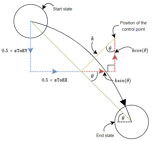
The arrowhead for a curved smart edge was positioned and angled in a very
similar manner to the arrowhead for a straight smart edge. The only difference
is that instead of using sToEX and sToEY, a different pair of translates
were used: cToEX and cToEY, representing the translation needed to get from
the control point to the end state. I had to resort to using this translation as
I was unable to calculate the tangent to the curve at the point where it crosses
the circumference of the end state. As long as the two states are not very close
to each other, the translation does a fairly good job of approximating the
tangent.
Loop edges use a cubic Bézier parametric curve segment as their edge and so have two control points instead of one. However, because loop edges connect a state to itself, calculating the bindings for the control points was not as difficult as calculating the bindings for the control point of a curved edge.
First of all, the start and end points of the curve are bound to the centre of the state, but with a horizontal offset subtracted or added to move them to the far left and far right sides of the circumference (these horizontal offsets are shown in the figure below as dotted blue lines).
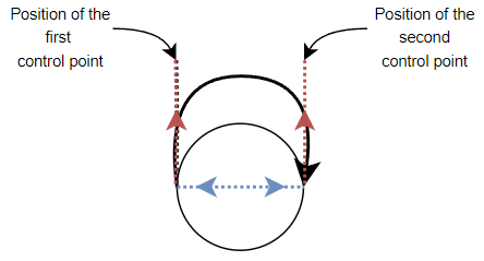
The two controls points are also bound to the centre of the state, but their offsets move them directly above or directly below the start and end points (recall that a user can decide whether the loop edge is above or below the state). The offsets for the control points can be seen in the figure above by considering the dotted blue and red lines together.
Controllers
This project uses the Model-View-Controller (MVC) design pattern to separate classes with different concerns.
- Models deal with storing and manipulating data. An example of a model is the
Parserclass, which manipulates regular expressions. - Views are concerned with the presentation of the program. They are implemented through the use of JavaFX FXML files.
- Controllers are responsible for user interaction. Each view has its own controller.
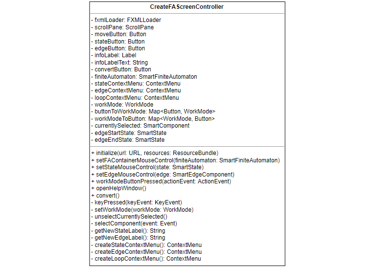
The CreateFAScreenController class
The CreateFAScreenController class is the controller for the view that is used
to create finite automata. The controller implements the logic that allows the
user to create states and edges, move states around the workspace, rename labels
etc. It does this by defining a WorkMode that changes how the user is able to
interact with the workspace. The user can switch between different work modes by
using the buttons in the toolbar at the bottom of the screen, or by using the
number keys on the keyboard. There are three available work modes:
-
In the
MOVEwork mode, the user can move states around the workspace by dragging them while holding the left mouse button. The user can drag states outside the right and bottom edges of the window to increase the size of the workspace. States cannot be moved past the left and top edges of the window. -
In the
STATEwork mode, clicking on the workspace with the left mouse button will create a new state at that location. -
In the
EDGEwork mode, the user can create new edges between states by holding down the left mouse button while on top of on one state and releasing it while on top of another state (if the start state and the end state are the same, a loop edge is created instead).
Each finite automaton component also has its own context menu, which is opened when the user right-clicks on the component. This is available regardless of the current work mode. The context menus allow the user to perform different actions on the components:
- The context menu for states allows the user to rename the state, set the state as the initial state, set the state as the final state and to delete the state.
- The context menu for edges allows the user to rename and delete the edges.
- The context menu for loop edges allows the user to rename, flip and delete the loop edges.
Renaming a state or edge will open a small window where the user can type in the new label. The user will not be able to press the Submit button to confirm the new label unless it meets the requirements for that component. States and edges have different requirements for their labels.
Whenever the user interacts with a component, that component becomes selected. Selecting a component highlights it and sets it as the target of any actions. For example, opening the context menu for a state will automatically select it. If the user then chooses the Delete option, the program will know which state it needs to remove.
The ConvertFAScreenController class
The ConvertFAScreenController class is the controller for the view that is
used to convert finite automata into regular expressions. Just like the
CreateFAScreenController class, it defines the user interaction behaviour for
the components of a finite automaton. In this view, the user is able to move
states around the workspace, but they can no longer create new components or
change existing ones (the only exception are loop edges, which can still be
flipped).
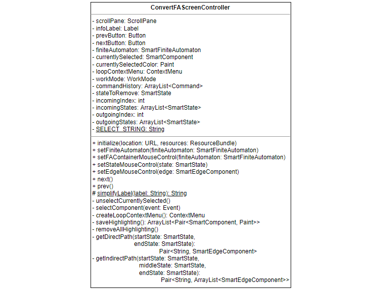
The ConvertFAScreenController class also contains methods that help in
converting finite automata into regular expressions. The getDirectPath method
returns the direct path (i.e. the edge) between two states. By calling this
method repeatedly, the getIndirectPath method is able to obtain the indirect
path between two states via a third state. The labels of these paths are then
combined and simplified using the simplifyLabel method.
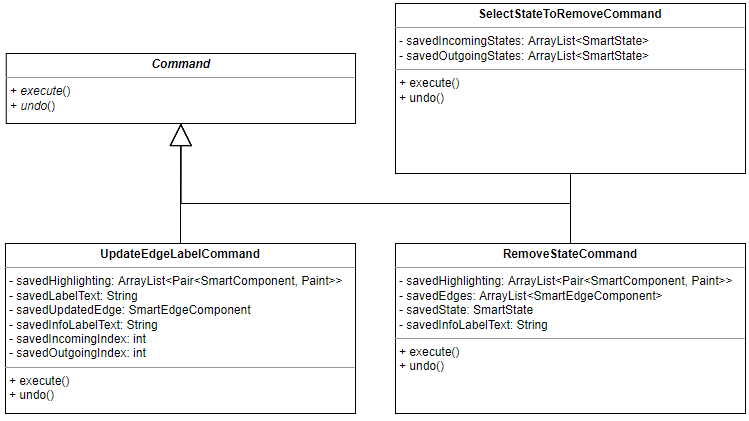
The conversion process itself was implemented through the use of the Command
design pattern. This design pattern turns an action into its own class that
contains all the information about the action. By storing this information, it
is possible for the action to be undone. The abstract class Command represents
all possible commands. The class consists of two abstract methods. The execute
method performs the action represented by the command. It saves the values of
any variables it changes to allow the action to be undone. When the undo
method is called, these variables are returned to their original values.
For the conversion of a finite automaton into a regular expression, three
commands were created. The SelectStateToRemoveCommand represents the action of
the user selecting which state of the finite automaton to remove in the next
iteration of the State Elimination algorithm. The UpdateEdgeLabelCommand
represents a single update step of the algorithm, where the label of one edge of
the finite automaton is updated to reflect the chosen state being removed.
Finally, the RemoveStateCommand removes the state from the finite automaton.
The ConvertFAScreenController keeps track of which command to call next
through the use of a WorkMode (note that this is not the same WorkMode as in
CreateFAScreenController). There are three available work modes, one for each
of the three commands: SELECT, UPDATE and REMOVE. When the user presses
the Next button, the next method is called. This in turn calls the execute
method of the command corresponding to the current work mode. The command is
also added to a stack representing the command history. When the user presses
the Prev button and the prev method is called, the command at the top of the
stack is popped and its undo method is called. This will undo the effects of
the last performed action. This functionality allows the user to go back and
revisit a previous step of the algorithm, for example so that they can try
removing a different state.
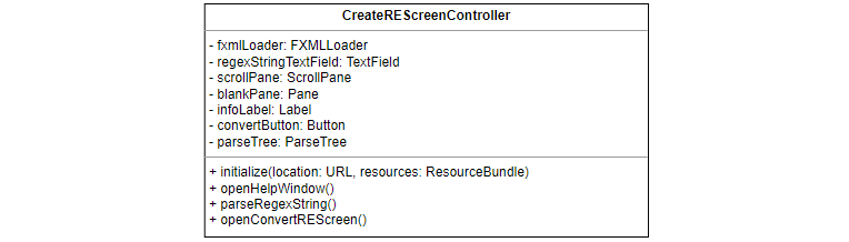
The CreateREScreenController class
The CreateREScreenController is the controller for the view that is used to
create regular expressions. Compared to the controllers for finite automata,
this controller is very simple. The parseRegexString method is called when the
user clicks the Parse button. The regex string entered by the user is parsed by
the identically named method of the Parser class. If the regex string is
invalid, the error message thrown by the method is displayed to the user.
Otherwise, the ParseTree for the regular expression is built and displayed.
This also activates the Convert button, which allows the user to switch the view
to the screen for converting regular expressions into a finite automata.
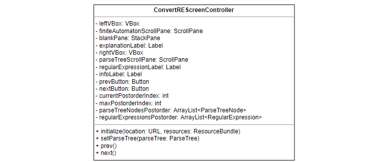
The ConvertREScreenController class
The ConvertREScreenController is the controller for the view that is used to
convert regular expressions into finite automata. The process is set off by the
setParseTree method, which is used to pass the parse tree (and by extension
the regular expression) created in the previous screen to this controller. The
setParseTree method gets the postorder traversal of the parse tree and of the
regular expression by calling their respective postorderTraversal methods. It
then highlights the first parse tree node and displays the finite automaton for
the first regular expression. The finite automaton is created by passing the
regular expression to the buildFiniteAutomaton method of the
GraphicalFiniteAutomatonBuilder class. The various labels on the screen are
also updated.
The prev and next methods work in a similar manner: they highlight the
previous/next parse tree node and display the finite automaton for the
previous/next regular expression. This allows the user to step forwards and
backwards through the different steps of the McNaughton-Yamada-Thompson
algorithm.
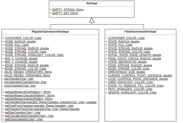
Settings
During the implementation of the program, various decisions had to be made about
its looks and to a lesser extent its functionality. Many of these decisions were
not technical in nature but just personal preference; for example, the radius of
a state in a finite automaton. To avoid the problem of magic numbers and to
allow these decisions to be easily changed, each decision was stored in its own
variable. However, it would be desirable to allow the user to change those
decisions to suit their own preferences and needs. While this is not possible in
the current iteration of the software, in order to future-proof the code the
Settings class and its subclasses were created. These classes contain all the
customisation variables. In the future, these variables could be modified from
being public static final variables to being private static variables. Getter
and setter methods could then be added to allow the user to modify them. These
methods have already been created for the symbols used as regex operators.
Testing
To ensure that the program functions correctly, a range of automated tests were written by using the JUnit testing framework. These tests are comprised of both positive and negative unit tests and focus on the backend logic of the program as opposed to the GUI. This allowed for regression testing to be carried out every time the code was changed, to ensure that the functionality of the program was not affected. Over 100 test cases were written.
Documentation
In addition to the usual code comments, Javadoc comments were written for all classes and methods. These comments describe what the class/method represents and what it is used for, as well as other useful information. For methods, they also list and explain the parameters and return values of the methods, as well as any exceptions thrown. Comments may also contain references to other related comments.
Conclusion
FAREC was a difficult project that posed many challenges. However, I was able to overcome most of them and the project was an overall success. Despite the complex theory involved, I believe my implementation to be both simple and elegant. Whenever possible, I tried to break down problems into smaller parts that could be more easily understood, implemented and managed. Due to the nature of regular expressions and finite automata, I was able to use recursion a lot, which proved to be an invaluable tool.
To correctly position the various edges used by smart finite automata, I made use of Properties and Bindings. These were concepts that I had encountered before, but I now had to delve deeper into their functionality. By the end of the project, I felt that I had a much better understanding of them. I am certain that they will prove useful to me in the future.
Something completely new that I learned while creating FAREC is the Command Design Pattern. I used this during the finite automata –> regular expression conversion process, to allow the user to step both forwards and backwards through the algorithm. Initially, I was worried that the design pattern would be hard to understand or implement, but it turned out to be very straightforward. This is another piece of knowledge that I hope to keep in mind for future use.
To package the program, I created a custom runtime image using jlink. While this works without issue on Windows, unfortunately I was not able to get it working on other operating systems. This is something that I definitely want to learn more about in the future.
For more information about the project or the theory behind it, please see the full report and project video.